Contacts (reed, proximity switches, Hall, pneumatic)
To monitor the flow rate, most flowmeters can be equipped with contacts.
The most common contact types are reed contacts and inductive proximity switches,
which are described in more detail below.
Reed-contacts
The reed contact is a potential-free contact, i.e. no additional auxiliary energy is required for the actual switching process. They consist of a glass tube filled with inert gas in which contact tongues are fused. The switching is done by the magnets built into the float of the flow meter.By using magnets or magnet packs of different strengths and reed contacts with different response sensitivities (AW number) or also limiting the float stroke, it is possible to realise a precise switching
The reed contacts are installed in a contact housing with plug or cable connection and are normally mounted adjustably on the flow meter.
Switching function - reed contact
The following switching functions are available:- Normally open contact (NO) - 2-pole
The two contact tongues are open and the circuit is only closed after the desired flow value has been reached and the magnets embedded in the float close the contact tongues of the reed contact. - Change-over contact (SPDT= Single Pole Double Throw) - 3-pole
The changeover contact has 3 contact tongues, i.e. when the desired flow value is reached, the contact switches from one pole to the other.

Contact type - Reed contact
In terms of the switching function, a distinction must be made between monostable and bistable contacts.- monostable
The monostable reed contact only has a "wiper" function, i.e. the contact tongues of the reed contact are only closed when the desired flow value is reached. If the flow value continues to increase, the contact opens again.
In order to obtain an unambiguous switching state, the manufacturer restricts the path of the float and the magnetic field in the float is optimally adapted to the response sensitivity of the contact.
The user can also use a switching relay with a latching function. This requires 2 switching pulses to change the switching state (1st pulse: float reaches the limit value, 2nd pulse: float falls below the limit value again after passing the limit value). - bistable
Bistable reed contacts have a unique switching function, i.e. the contact is closed when the desired flow value is reached or exceeded and opened when the flow is less than the set limit value. This is achieved by pre-magnetising the contact tongues of the reed contact, e.g. by an additional small magnet on the reed contact. This small force is sufficient to keep the contact straight in the respective position, but not to trigger a change in the switching state. Only the additional magnetic force of the float triggers the switching state.
When the float rises, the magnetisation of the contact tongues is increased and the contact tongues close. When the float falls, the other magnetic pole in the float weakens the magnetisation and the contact reeds open.
Inductive proximity switches
Inductive proximity switches are sensors that switch without contact when a metallic float approaches.For this purpose, an alternating electromagnetic field is generated in the sensor by means of an oscillator, which is conducted to the active surface of the sensor and exits there. If a metallic object approaches this active surface, eddy currents are generated which draw energy from the oscillator. A switching signal is generated from this by downstream electronics integrated in the sensor. Different switching functions (NPN/PNP, normally open, normally closed, etc.) are available.
The inductive proximity switch must be supplied by an external auxiliary power. For this purpose, switching relays are often used, with which a higher switching capacity can additionally be realized.
Different designs are used for variable area flowmeters:
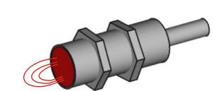
- Rod shape sensor
These are usually mounted slidably outside a non-metallic measuring tube. The active electric field is located on the front side of the sensor.
Since the sensors only work up to a maximum switching distance, a precise selection of the sensor must be made.
This is especially true for variable area flowmeters for large flows where there is a large distance between the float and the sensor in the upper measuring range. At the same time, the distance between the float and the sensor in the lower measuring range is small and, if sensors with a large switching distance are used, this can be influenced by other metallic components; e.g. a metallic protection tube for a glass measuring tube.
- Ring sensor
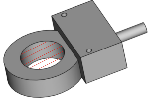
These are mostly used with variable area flowmeters for smaller flows, and thus measuring tubes with small diameters. They are located around the measuring tube and are slidably mounted outside a non-metallic measuring tube.
The active electric field is located inside the sensor ring and is therefore not susceptible to metallic parts outside the sensor inner diameter.
- Slot sensor
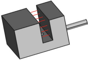
These are mostly used with variable area flowmeters with metallic measuring tubes.
In this case, a metallic vane is mounted on the pointer mechanism, which is immersed in the switching plane of the sensor. The active electric field is located between the two legs of the sensor.
Valves
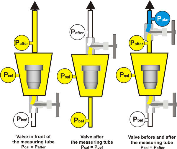
To adjust the flow rate, the units are often equipped with an adjustment valve. This can be a valve installed externally in the pipeline or a valve that is integrated into the fitting of the flow meter. Depending on the fluid used, different installation positions should be provided.
-
Liquids
Liquids are not compressible and the arrangement of the valve can be chosen as desired. Usually the valve is mounted in front of the unit. -
Gases
Gases are compressible and the pressure conditions in the measuring tube (pkal) have a decisive influence on the measuring accuracy of the flow meter.
Der bei der Kalibrierung der Geräte zugrunde gelegte The operating pressure (pkal) used as a basis for calibrating the devices should be maintained and constant. The position of the valve is therefore usually behind the meter.
For measurements against constant downstream pressure (pnach), e.g. atmospheric pressure, the valve can also be mounted in front of the device.
Analogue output / totaliser
In the case of standard variable area flowmeters, the measured value is read on site, either on the
scale attached to the measuring tube or, in the case of units with a metallic measuring tube,
on a pointer display mounted on the unit.
This is usually sufficient, especially for smaller systems, and ensures measurement even
without auxiliary power or if the auxiliary power fails.
However, due to increasing automation or in the case of larger systems, it is necessary to
transmit the measured flow value to a control room or to a control system.
Traditionally, this was done on instruments with magnetically guided pointer indicators by
mechanically connecting the pointer axis to a moving coil instrument. This converted the rotary
movement of the pointer axis, and thus the measured value, into a resistance value (potentiometer
principle).
The resistance is a wire (moving coil instrument) or, in the case of modern instruments, a conductive
plastic disc is used.
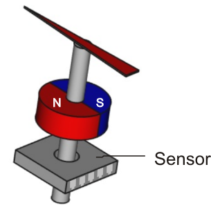
Modern instruments today often use magneto-electric angle transducers in which a permanent magnet
mounted on the pointer axis transmits the rotary movement of the pointer to a magnetic field sensor.
Depending on the rotational position of the magnet, the magnet field lines have a different position.
These are detected by two Hall sensors in the sensor element that are perpendicular to each other.
This Depending on the position of the field lines, a different signal voltage results which can be
assigned to an angular position of the pointer.
This principle also works to some extent with devices with transparent measuring tubes and permanent
magnets embedded in the float.
The moving coil instrument or magnetic field sensor is followed by electronics that convert the signal into a standardised analogue output (0)4-20 mA, 0-(5)-10 V or binary signals.
Advanced electronics have communication interfaces such as Profibus®, Fielbus®, Hart®, etc..
Often the non-linear measuring scale is also converted into a linear output signal by the downstream electronics.
To sum up the total amount of fluid that has flowed through, electricity meters adjusted to volume units (e.g. m³, Nm³, etc.)
are integrated.
The latest generations of units have a menu-guided LED display with which the unit display or the output can be programmed.
Among other things, the measured variables can be displayed, e.g. in operating volume, standard
volume or mass flow, the units in (Nm³/h, NL/min, Kg/s etc.), the counter function, error/service messages (e.g. maintenance, failure).
The setting of the output, the setting of the contacts, etc. are freely configurable.
Magnetic filter
Variable area flowmeters are suitable for flow measurement of clean, particle-free fluids.
Larger dirt particles can cause the float to jam.
Therefore, dirt filters are mounted in front of the unit.
However, even the smallest ferromagnetic particles that are not retained by the dirt filter can
deposit on the magnets of the float and build up a disturbing coating.
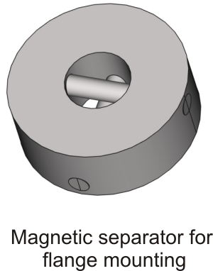
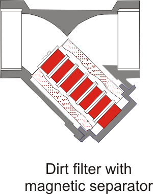
A remedy is provided by magnetic separators, which are available in a wide variety of designs, e.g.
magnetic separators with encapsulated, spirally arranged magnets for intermediate flange mounting,
or dirt filters with an integrated magnet package as magnetic separators.
Up-/Downstream Pressure Regulator
Changes in the pressure conditions (upstream or downstream pressure) in the pipeline also change the
set flow rate. By using a upstream or downstream pressure regulator, this pressure fluctuation can be
compensated within certain limits and thus the flow rate can be kept constant.
A complete measuring device consists of a permanently mounted variable area flow meter, valve and
differential pressure regulator. The differential pressure regulator consists of a housing and a
diaphragm.
After the flow has been set to the desired value at the valve of the flow meter, the diaphragm of the
differential pressure regulator is in a state of equilibrium, the pressure on both sides of the
diaphragm is the same.
If the pressure changes on the inlet or outlet side, depending on the type of regulator, the pressure
is equalised via the diaphragm valve until the diaphragm is in equilibrium again and the flow
corresponds to the set value. In order to function properly, the regulators require a minimum pressure
and they are limited by a max. permissible pressure.
There are 2 types of differential pressure regulators.
- Upstream pressure constant, downstream pressure fluctuating

- Downstream pressure constant, upstream pressure fluctuating

Lining of the measuring tube
When selecting a variable area flowmeter, it is important to ensure that the materials used in the
device are resistant to the fluid to be measured.
Therefore, glass or resistant plastics are often used as material for the measuring device.
The disadvantage of these materials is that they cannot withstand higher operating pressures.
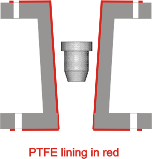
Therefore, measuring devices with metal tubes must be used, which have a higher pressure resistance and
are made of high-quality metal (e.g. Monel, titanium, Hastelloy, etc.) for chemical resistance. Since
these metals and the manufacture of a flow meter from these materials is expensive, a device with a
lining of Teflon can often be used as an alternative.
This results in a device that is both chemically resistant and pressure resistant.
Thermal insulation / heating
For some fluids to be measured, it is necessary that the fluid in the variable area flowmeter
does not cool down or heat up. Often it is sufficient to use a meter with a magnetically guided
display and corresponding external insulation of the measuring tube by the customer.
For higher requirements, additional electrical trace heaters are used, which are wrapped around
the outside of the measuring tube.
Further information on electric trace heating, e.g. on the website of the company Bartec.
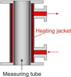
In the case of extremely difficult media or ambient conditions, it is recommended to use
double-walled measuring design should be used. These consist of an inner measuring tube and a tube
around it through which a heating/cooling liquid (thermo-oil, steam or water) flows and thus keeps
the fluid at the desired temperature.
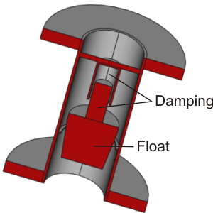
Float damping
In order to avoid pulsation of the float due to compression pulsation,
variable area flowmeters can be equipped with float damping.
Depending on the manufacturer or unit design, different versions can be found on the market.
However, the basic principle is usually based on the "shock absorber principle", as
it is also used in car shock absorbers.
For this purpose, a piston is mounted on the head of the float. A cylinder, closed on one side,
is mounted opposite in the measuring tube. The piston moves into the unilaterally closed cylinder
and the medium inside is compressed.
The medium in the cylinder is pressed out through the annular gap between the piston and cylinder
with a time delay, thus creating damping.
In some applications, an additional damping spring is mounted outside the damping cylinder.
The float damping can also be retrofitted by some manufacturers or unit types.
Due to the additional piston and the associated higher weight of the float, the scales must
be recalculated.
