Calculation of a variable area flow meter
A varaible area flowmeter (also known as a rotameter) is a mechanical measuring instrument
used to determine the flow rate of gases and liquids.
The measurement is based on the balance of forces between the flow force, the weight of
the float and buoyancy.
Balance of power
A variable area flow meter essentially consists of two main components:- A conically shaped pipe that is mounted vertically and in which the cross-section of the pipe increases towards the top.
- A floating body that can move freely in the measuring tube. The flow of the medium acts upward, while the weight pulls the floating body downward.

The float settles at a fixed height in the measuring tube as soon as a stable equilibrium of forces is achieved. The upward-directed flow force FW is reduced by the downward-acting weight force FG and balanced by the buoyancy force FA.
FW = FG - FA
The height of the float is therefore a direct measure of the flow rate of the medium. As the volume flow increases, the flow force increases, causing the float to move further upward.
- Flow force FW
The flow force FW, which pushes the float upwards, depends on the flow rate and the aerodynamic properties (shape) of the float. It is calculated using the formula known from aerodynamics.
FW= 0,5 ⋅ ρR ⋅ v² ⋅ CW ⋅ A
ρR: Density of the medium in the annular gap between the float and the measuring tube. [kg/m³].
This can deviate from the normal medium density (ρM) in compressible media (gases).
As ρR is difficult to calculate, the normal medium density (ρM) is often used in practice.
The difference is taken into account by the empirically determined CW-value.
v: Flow velocity of the medium in the annular gap[m/s]
CW: Drag coefficient (depending on the shape and surface properties of the float),
the surface of the measuring tube and the Reynolds number [dimensionless]
A: Cross-sectional area of the float (projection area = largest diameter) [m²]
- Weight force of the float FG
FG= ρS ⋅ VS ⋅ g
ρS: Density of the float [kg/m³]
VS: Volume of the float [m³]
g: Acceleration due to gravity 9.81 [m/s]
- Buoyancy of the float FA
A= ρM ⋅ VS ⋅ g
ρM: Density of the medium [kg/m³]
VS: Volume of the float [m³]
g: Acceleration due to gravity 9.81 [m/s]
- Relationship between flow velocity and volume flow
The flow velocity v of the variable area flow meter is directly related to the volume flow Q
Q= v⋅AR
v: Flow velocity of the medium in the annular gap [m/s]
AR: Free cross-sectional area between float and measuring tube, at the position of the float [m²].
This is the gap through which the medium can flow.
This area changes with the height of the float.
In order to determine the theoretical volume flow of a variable area flow meter in the “floating state”, i.e. a certain height in the measuring tube, the above formulas of the individual forces are used in the basic equation.
FW = FG - FA
The result is:0,5 ⋅ ρR ⋅ v² ⋅ CW ⋅ A = (ρS ⋅ VS ⋅ g) - (ρM ⋅ VS ⋅ g)
If v² is replaced by the above formula for the volume flow Q, the final formula for calculating the volume flow is obtained after conversion and simplification:

ρR: Density of the medium in the annular gap [kg/m³]
ρS: Density of the float [kg/m³]
VS: Volume of the float [m³]
g: Acceleration due to gravity 9.81 [m/s]
AR: Free cross-sectional area between float and measuring tube, at the position of the float. [m²].
CW: Drag coefficient (depending on the shape and surface properties of the float) [dimensionslos]
A: Cross-sectional area of the float (projection area = largest diameter) [m²]
In a given variable area flow meter, the density of the float, the dimensions and volume of the
float, the density of the medium and the acceleration due to gravity remain constant when the
flow rate changes.
When the flow rate changes, only the drag coefficient and the free cross-sectional area between
the float and the measuring tube change (corresponding to the lift height of the float).
As this dependency cannot be determined purely by calculation, it must be determined
empirically by calibration.
Factors influencing the calculation
- Density of the medium
- Viscosity
- Geometry of the float
- Installation position and diameter of the measuring tube
Practical calculation of a variable area flow meter
In order for a conical pipe with a floating body to be used as a flow meter, the device must first be calibrated. Calibration is usually performed on a test bench by comparing measurements with other, more accurate measuring devices; alternatively, by weighing or measuring the volume of fluid that has flowed through per unit of time.
The flow values (scale) determined for different heights of the float only apply to
the fluid used during calibration under the operating conditions present at that time.
If the devices are to be used for other fluids (with different densities and viscosities) or
under other operating conditions (pressure and temperature), they must be recalibrated.
Research by G. Ruppel and K.-J. Umpfenbach has shown that it is also possible to
convert an existing scale to other fluids and/or operating conditions.
On this basis, various manufacturers have developed calculation routines, which have then
been standardized in VDI 3513 Sheet 1.
Calculation of a scale for variable area flow meters
In practice, the following formula, derived from the equilibrium of forces, is used to calculate the volume flow rate.

If, instead of DIN units, the units listed below, which are commonly used in
practice, are used in the calculation, the correction factor (C) must also be included
in the formula.
To simplify the formula, this factor contains not only the unit correction but also the
constant value from √g.

α= Flow rate, depending on the geometry of the float, the measuring tube,
the properties of the medium and the flow conditions (laminar/turbulent).
Also referred to caalibration factor.
C = Correction factor [11,27]
Ds = Diameter of the float at the reading edge (max. diameter of float) [mm]
ρ= Density of the measured medium [g/cm3]
g = Acceleration due to gravity [9,81 m/s]
Ms = Mass of the float [g]
ρs = Density of the float [g/cm3]
Ruppel-Number
The Ruppel number is a dimensionless parameter derived from the Reynolds number.
In a floating-body flow meter calibrated for a specific medium, the Ruppel number is independent of
the height position of the floating body.
It depends on the density and mass of the floating body and the viscosity and density of the medium.

g = Acceleration due to gravity [9,81 m/s]
Ms = Mass of the float [g]
ρ = Density of the measured medium [g/cm3]
ρs= Density of the float [g/cm3]
Characteristic curve or table
Manufacturers use tests to determine how the Ruppel number (Ru) depends on the flow coefficient
(α) for different diameter ratios (δ) for each combination of measuring tube and floating
body and for different measuring substances.
The results are documented in characteristic curves or tables.
Some manufacturers supply these characteristic curves or tables directly with the flow meter.
This allows customers to read the α values required for calculating a new scale, matching the
calculated Ruppel number and for different diameter ratios (δ).
The annular gap between the float and the measuring cone is decisive for the flow rate:
The higher the float rises, the larger the annular gap becomes.
The diameter ratio δ is calculated as a dimensionless number from the height of the float and
is shown in the characteristic curve sheet:

D= Diameter of float [mm]
The diameter ratio is assigned by the manufacturer of an mm scale, a % scale, or an existing scale. Some manufacturers use the opening ratio (δ-1) instead of the diameter ratio as a measure of the position of the float.

Example of converting a scale
Floating body / Measured substance Input
Calculation of Qv based on the α values read
The calculations are performed using sample values.
Adjustment to your variable area flow meter.
You can replace all values for the float, measuring medium 1, and measuring medium 2
with your own values and calculate the corresponding Ruppel numbers (Ru).
Using the Ruppel numbers, you can determine the respective α values from your characteristic
curve sheet.
After entering the α values in the table, your flow values [l/h] for the various
float positions are calculated.
The diameter ratio (δ) according to DIN from the characteristic curve is provided
as a reference to the calculated flow values.
You can also enter other values specified by the manufacturer for the height of the floating
body as a reference. Example: : [mm], [%], [m-value], [l/h old scale]
Modern calculation methods for scale creation
With modern numerical calculation methods, scales for variable area flow meters can now be
determined entirely by calculation. The scale is created based on the geometry of the flow meter
and the material-specific properties of the measuring medium—without the need for time-consuming
experimental calibrations.
Fluid-structure interaction analysis (FSI) is used.
This method describes the coupled physical interaction between the fluid (e.g., water or air) and the
structure of the measuring system, consisting of a measuring tube and a floating body.
In this way, the actual operating behavior of the flow meter can be simulated very precisely.
Initial calculations and fundamental work in this field were carried out by
Dr.-Ing. T. Chatzikonstantinou.
One disadvantage of this method is the high computational effort required, as powerful computer systems are
needed to perform the complex simulations efficiently.

Calculation of a scale at new conditions
The scale of the variable area flowmeters is designed in the factory for a specific fluid with properties (density, viscosity) and the operating conditions (pressure, temperature) at which the the device is used.
Most manufacturers provide design software for variable area flowmeter-conversion of a scale at new conditions, which can be used to specify the optimum device for the measurement task
Example for calculation software: http://sizing.heinrichs.eu/programs/schwebekoerper/de
The most common task for the user is to adapt the existing scale to the new conditions when operating conditions change or a different fluid is used. or when using a different fluid, to adapt the existing scale to the new conditions. Changes in the material properties and operating conditions of gases or liquids have different influences.
- Gases:
Gases are compressible, i.e. they change their volume and thus density when the pressure and temperature conditions change. Because of the low gas density and low viscosity, a change in density and viscosity with different gases usually has little influence on the measurement. - Liquids:
Liquids are normally non-compressible, i.e. they do not or only slightly change their volume and thus their density with changes in pressure and temperature.
A change in pressure and temperature does not normally have to be taken into account for the same fluid. However, other viscosity or density values for different liquids have a great influence on the measurement. It may also be necessary to take into account changes in the viscosity of the liquid caused by a change in temperature.
Factor calculation for gases:
Calibrated scale in standard volume (e.g. Nm³/h)New scale values = factor x calibrated scale values
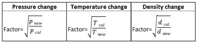
Kelvin = 273 + °C
Calibrated scale in operating volume (e.g. m³/h)
New scale values = factor x calibrated scale values
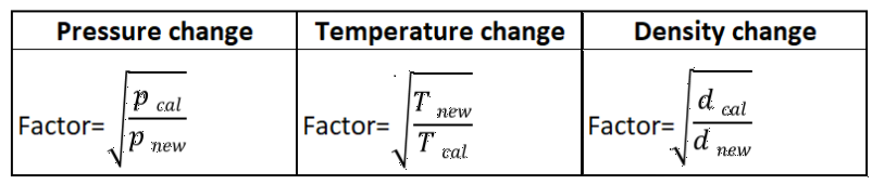
Kelvin = 273 + °C
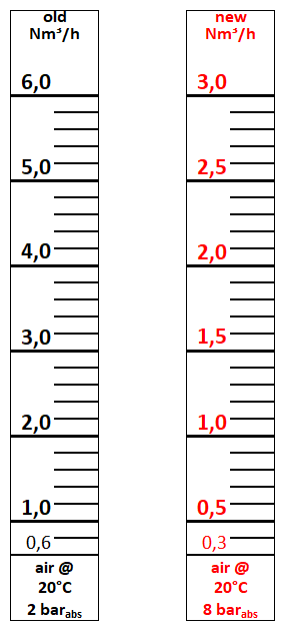
Example of an Nm³/h air scale calibrated at 2 barabs.. New operating pressure 8 barabs.
All technical articles published on pt100.de with attribution were written or reviewed by Harald Peters himself.
Author of this article:
Harald Peters – Technical author for flow measurement technology.